loading

Forum Forum

Go to forum

Positioning Mode Uniform Density

RSS
Udo Uschkerat 22/09/14 15:00

Dear Seamcat specialists,

I'm using seamcat for SE24 WI 37, UWB-LDC mitgation. To compute the interference probability a certain interferer device densitiy (100/km2) and activity factor (0.01...0.1) is used. When using MCL calculation the maximum simulation radius (distance ILT-VLR) should be 2.1km for ILT with -51.3dBm. This accounts to approx. 139 devices inside the 2.1km radius. I run the seamcat simulation and get an interf.prob. of 38.6% for I/N criterion. So far so good (you can see all details of the VLR in the attached file).

Now I can include more that 139 devices, it will increase the simulation radius. Since the additional devices will be outside the 2.1km radius they should not contribute to the interference probability, I'm just burning CPU power...

But since I'm opening a topic here, you guess it: the interf.prob. increases. What is wrong in my assumption?

I attach a simplified version where you can easily change the number of active devices, see the simulation radius increases and the interf. prob. also increases.

Looking forward to your comments!

Udo Uschkerat

[member was deleted] 23/09/14 12:49

Dear Udo,

In general, any interferer located inside the simulation radius contributes to the impact on the victim.

As you use for the relative positioning of the interfering transmitters "Uniform density", the number of active transmitters determines the simulation radius.
It is quite obvious that if leaving the figure of the density constant, an increased number of active transmitters enlarges the area and consequently the simulation radius. Therefore your main assumption of a "fixed interference radius" of initially about 2.1 km fails due to additional transmitters increase the simulation radius and then my first sentence applies J

Please allow me a comment on the values of the Interference criteria.
The used values are consistent themselves, but not consistent with the workspace. With a noise floor of -112 dBm and a sensitivity of -120 dBm, the "real" C/(N+I) becomes -8 dB and the value of C/I -1 dB. As long as you calculate the probability of exceeding the limit (misleadingly called 'probability of interference') only for the criterion I/N it doesn't matter. As soon as you would do it for instance for C/(N+I) you will get with your figures definitively wrong results (see the User manual).

Hope it helps.

Regards,
Karl

Udo Uschkerat 23/09/14 18:37

Dear Karl,

thank you for pointing out the C/I criteria.

Concerning the active transmitters per area, the number of transmitters inside an antenna beam will grow quadratically with n(r)=DevDensity*pi*r^2. If all active transmitters have the same power Ptx, the cumulative ILT power at the victim receiver can be described by the number of transmitters times 1/r^2 times Ptx plus LOS-Losses (well known path loss equation).

Using   Pvictim,receive (r) = Σ i=1..n(r)   (L_los * PILT,I

with PILT,I = Ptx*1/r^2 (include 1/r^2 here!)

the summation can now be written as
Pvictim,receive (r) =  n(r)*L_modified*Ptx*1/r^2

and L_modified=32.45 dB + 20×log[frequency(MHz)] 

Since n(r) =Ndev/km² *pi()*r^2,  Pvictim,receive (r) becomes independent from r!

Indeed, one gets a constant received ILT power, no matter how big r becomes.

So from theory the ILT device density should be a limiting factor, not the simulation radius.

My only suspect in the SEAMCAT results is the very different CDF of iRSS Unwanted when using the small simulation radius:

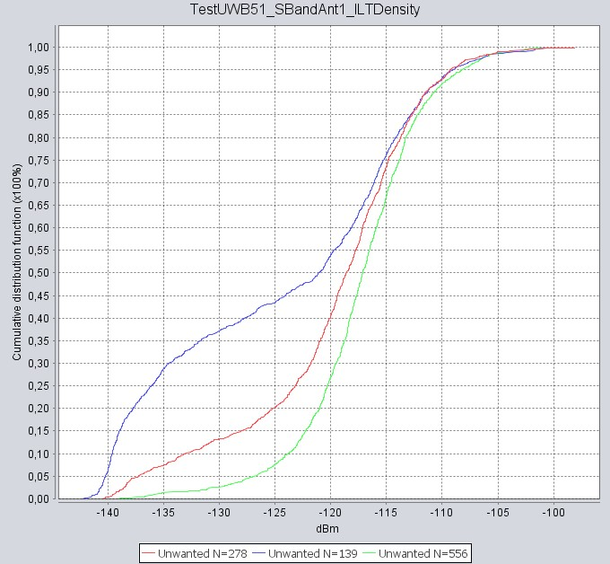
Here N=139 means Rsim=2.1km, N=278 gives Rsim=3km and N=556 gives 4.2km. I know, now I'm completely off-topic, and indeed, such kind of result is also seen when not using device density, but fixed number of ILT and fixed Simulation radius (mode "none"). Do you find the blue distribution curve also strange?

Thank you again for your help!

Edit: Ralf Kallenborn pointed me to ITU R-REC-SM.1757. In chapter 2.3 the mathematical concept to deal with device densities is explained. It's different than my assumptions above, finally the received power flux density will grow with the logarithm naturalis of the simulation radius.

So far, item is closed for me. Don't copy my thoughts above, there must be an error insight!

[member was deleted] 25/09/14 13:55

Dear Udo,

Thanks to Ralf for helping.

In order to allay your concerns about the vector distribution a comment.

The antenna you use for the VLR has a beam width of about 1.5 degree, fixed pointing to its VLT. The number of  ILTs inside the beam width is given by the density and the size of the area the beam width covers, i.e. indirectly by the simulation radius. The resulting distribution density looks for a very low number of active transmitters like this

which is quite far away from a Gaussian distribution.

The larger the number of active transmitter, the closer the distribution to the normal distribution.

Supposing that you use for all link types the same protection distance of 0.17 km, this has - with respect to number of ILTs inside the beam width - for the smallest simulation radius additionally the biggest effect.

You may try an omni-directional antenna and you will get for all systems the same distribution density.

Regards,
Karl

Close
Site will periodically be offline Monday 22nd April between 0800 CEST and 1200 CEST - IMPORTANT - please read here for changes in functionality after update
Do not show again